
Welcome
3D lovers
Welcome to my 3D work page. Here you will get to see the behind the scenes of my work and see the different models I have made.
Drone Research


The contents above was organised and drawn by myself however, information was found on the following site
Why?
Drones can be used for lots of things, such as observing natural disasters, photography, filming, and delivering goods. They are also used by the military for things such as surveillance and targeted attacks.


Sculpture
.jpg)

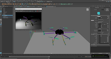
When starting the course, we were introduced to Maya through a simple sculpture assignment.
Some quick notes to remember:
-
Red axis marker - x
-
Blue axis marker - z
-
Green axis marker - y
-
Use spacebar to bring up 4 different views
-
Pan view - alt + mouse middle button
-
Rotate view = alt + left click (hold )
-
Zoom - alt + right click (hold)
-
Units within Maya is in cm
-
With whichever tool use coloured arrows or right hand numbers to make adjustments use the middle square to make adjustments to the entire shape.
-
Subdivisions are under "poly(shape)" in the inputs section.
-
Select polygon, right click to bring up modes
-
Face, vertex, edge. shift + right click gives you more advanced options.
-
In face mode holding down shift extrudes the shape.
-
Quick keys - w = move, e =rotate, r =scale, q = select.
-
Using references - Recognise where the view is. e.g. front, side, top.
-
Import reference - select - image plane and find the image you want.
-
Display right side of the screen add layer rename and lock
-
If you have too sections on a model, you can merge the vertices by shift + right - right click- vertices - merge
.png)
.png)
.png)
.png)
.png)
Drone Model

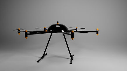
To start off the production of our drone, we started with the center of the model and worked our way out. This meant that we started with the drone hub. To do this we created a sphere from the shapes row and we had to then scale it to match the measurements on the design reference. The measurements that we were given to work with were put down as mm however, we needed them to be in cm so we had to divide the measurements we were given by 10 before making the different parts of the model.
For the drone hub, we had to make a sphere with a diameter of 350mm, so we converted this into centimeters which was 35cm. In order to create the sphere, Maya wanted us to find the radius of the shape we wanted to create so that the program could make the scale accurate. This came to 17.5cm. So we put this into the polysphere settings found on the right hand side of the screen. Once we put the number 17.5 into the radius section of the polysphere settings.
Still inside the polysphere settings, we then changed the subdivision axis of the shape to 32 (why?). After this we then flattened the bottom half of the hub using vertex mode. In order to get into vertex mode, we had to have the shape selected and then right click and hold to access the functions here. We then highlighted the bottom half of the sphere and squashed it up by scaling it along the y axis to create a hemisphere. The same was done with the top of the sphere so that it was following the properties of the drone reference so that the antenna has somewhere to sit on top of the drone.
For the antenna of the drone, we used the shape library to create a prism and placed this on top of our drone. Once scaled to the desired size and placed in the center of the drone hub, we beveled the edges (round them off). To do this we had to select the shape and go into faces mode. When we're in faces mode we then was to hold down shift and right click to find the bevel edges option.
Moving out, we started work on the arms of the drone. For this, we used the cylinder from the shape library and stretched them out to the appropriate length as well as rotating them to come out of the drone hub realistically. For the height of the arm/cylinder we had to make it 60cm with a radius of 1.4 and we had to make sure that the y axis setting remained 1. Once this was done, we then used vertex mode to shorten the end of the cylinder inside the drone hub and scaled down the outside end of the arm so that it grew smaller the further out we went.
On the end of the arms of our drone, we required motors. For the motors, we created a cylinder with a height of 6cm and a width of 1.5cm. Following this, we made a sphere for the top of the motor. This sphere had a radius of 1.5cm to match the width of the motor. We then deleted the bottom half of the sphere as keeping it was not necessary and placed it on top of the motor. For the tip of the motor, we went into vertex mode and pressed b and held and dragged to select the tip of the shape. We then moved this upwards to make the tip more pointed. This was repeated for the base of the motor as well.
For the connection between the drone hub and arm, we used the pipe polygon. This was found in the prism drop down menu. To start, we rotated the pipe 90 degrees and gave it a radius of 2 so that it could fit around the arm. We then deleted the bottom of the pipe to match the drone image/reference. After this, in edges mode, we selected the relevant edges and held shift to select both sides. Once all of this was selected, we dragged both sides down to make them the right length and then we filled the hole so that there wasn't a gap at the bottom of it.
After working on the main frame for the arms, we started work on the propellers to attach to the motors. For the propellers, we opened up a new document in Maya and made a reference plane on the top view perspective and locked this layer to avoid accidental changes to the image. We then added a cube into out scene with subdivisions of a width of 5, height of 2 and a depth of 3. We then squashed this down to make the box as thin as we wanted our propellers wings to be. Using vertex mode, we then moved out the different parts of the propeller to fit the reference image. This was followed by twisting the blade, which we did by rotating of a single row of vertex's at a time. We then saved this scene and went back into our original drone scene (the one containing the drone hub and arms) and we imported the propeller document we just saved into our scene. However, both the propeller and the reference would be imported so we had to remove the reference from the scene. After this we have to clone the propeller so that it is sitting on either side of the motor at the end of the arm.
Extra
Use D to set/change the pivot point you can then move it to wherever (this will help you move/make/clone the other arms) .
Drag the symbols next to the name into other names in order to group them
(Grouping quick key - ctrl + g )

.png)
.png)
.png)
.png)
.png)
.png)
Robot


Electric technology
Task:
You will create a 3D model of a real-world object, which will be allocated to you and based on the items listed below. You must gather and document your own asset relevant research, reference material and sketches. Using only Autodesk Maya and Arnold, you must employ suitable polygon modelling techniques and apply appropriate materials and textures to closely resemble the original real-world object:
-
Model the necessary components to create the asset.
-
The 3D model creation must be a close representation as to the referenced object.
-
You must create at least two original material/shader consisting of appropriate texture maps (diffuse, roughness, bump) using Adobe Photoshop and apply to relevant parts of the 3D asset. Evidence of the development these original materials must be clearly shown in your blog.
-
Use appropriate UVW mapping and unwrapping techniques to accurately size and position the applied textures.
-
Develop and create a suitably lit studio environment to best show the quality of your modelled and textured asset (LookDev).
-
You must create at least three final rendered images to best show the complete modelled and textured asset.
-
In order to achieve this, you will create and position several suitable cameras
-
Final rendered images must be of a high quality and a minimum 2k pixels at an orientation and aspect ratio to best suit the final composition.
-
All work must be clearly and chronologically evidenced in your personal learning blog. This will show a visual development of your asset creation and include concept sketches, design artwork, reference images, evidence of the 3D modelling process and at least three rendered images.
-
All scene files and related assets must be saved to the relevant Maya project folders.
-
Consider that your work could be passed onto another department when working in industry. Naming conventions for both objects and textures must be observed on all submitted files.
Coffee maker


_jfif.jpg)

A coffeemaker, coffee maker or coffee machine is a cooking appliance used to brew coffee. Altogether, there are 10 types of coffee makers:
Electric:
-
Drip Coffee Makers
-
Thermal Coffee Makers
-
Espresso Machines
-
Percolators
-
Siphon Coffee Makers
Manual
-
French Press Coffee Makers
-
AeroPress
-
Cold Brew Coffee Makers
-
Vietnamese Coffee Makers
Stovetop
-
Moka Pot Coffee Makers


Drip Coffee Maker

Precolator
_jfif.jpg)
Thermal Coffee Maker
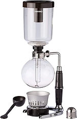
Siphon Coffee Maker

Espresso Machine

French Press Coffee Maker

AreoPress

Cold Brew Coffee Maker

Vietnamese Coffee Maker

Moka Pot Coffee Maker
For more information on each of the individual coffee makers, click on the image.
The information from these images was found on the following website:
https://coffeeaffection.com/different-types-of-coffee-makers/
_jfif.jpg)


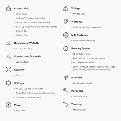
The Bambino® Plus
Measurements :
- 20cm W
- 32cm D
- 31cm H
Materials:
- Stainless Steel
Tamper - 5.4cm
Views/angles


.png)
Behind the scenes character work
Here are some of the character head I have pre


